From infotainment to advanced driver assistance systems (ADAS), today’s vehicles rely on the flow of large volumes of data, a flow which is beginning to be constrained by the capacity of established automotive bus architectures such as CAN bus. In response, the automotive industry has developed a version of the ubiquitous Ethernet networking standard for use in vehicles.
However, debugging these automotive Ethernet networks is not a trivial task, which is leading developers to seek out new test solutions. The 100BASE-T1 Ethernet interface, based on BroadR-Reach technology, has now been standardized by the IEEE 802.3bw working group. Implementing automotive networks with this new standard brings a host of development changes, including the 100 Mbit/s data rate that is significantly greater than traditional bus systems.
Featuring full-duplex Ethernet communications over an unshielded Ethernet twisted pair, 100BASE-T1 signals have PAM-3 modulation and differential signal levels of between –1V and +1V. The transmitted signals have to be pre-distorted by an equalizer so that they can be carried reliably and with minimal RF leakage over an unshielded cable. It is this extensive pre-distortion applied to a 100BASE-T1 Ethernet signal that makes it difficult for developers to judge the effectiveness with which a bus is carrying data by simply analyzing its electrical signals.
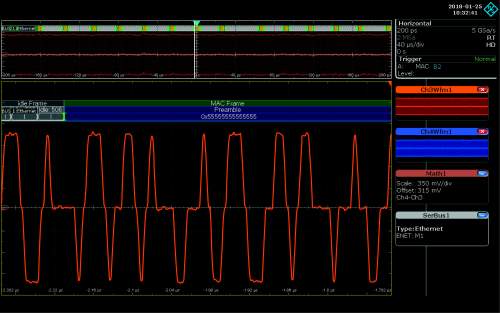
Figure 1a : A differential 100BASE-Tx signal, showing its three levels and the steep edges at the signal transitions. Source: Rohde & Schwarz
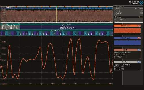
Figure 1b: An automotive 100BASE-T1 signal, showing how pre-distortion masks the three levels of the PAM-3 signal. Source: Rohde & Schwarz
The automotive Ethernet test challenge
Standardized compliance tests for 100BASE-T1 interfaces involve measuring electrical characteristics using an oscilloscope and network analyzer. An Ethernet protocol analysis tool that records all of the Ethernet data traffic can be used to verify that an electronic control unit (ECU) correctly handles communications. Beyond this, however, it is difficult to perform detailed root-cause analysis because transmission errors are only recorded as telegram errors.
To perform more in-depth analysis it becomes necessary to combine a suitable trigger and decode bundle with the chosen oscilloscope. By enabling developers to directly correlate electrical signals with the transmitted telegram content, for example, Rohde & Schwarz’s trigger and decode bundle for 100BASE-T1 makes it possible to debug bus issues in automotive Ethernet applications as easily as it has been traditionally for CAN bus implementations.
Addressing the testing challenge
Because 100BASE-T1 communication is based on simultaneous transmission of bi-directional data, any signal measurement on the bus extracts superimposed data streams. To analyze the two data streams, they must be separated, using directional couplers such as those found on the R&S RT-ZF5 Ethernet probing fixture. Inserting the probe in the Ethernet line separates the data streams, allowing an oscilloscope to be used for non-intrusive recording of the 100BASE-T1 communications.
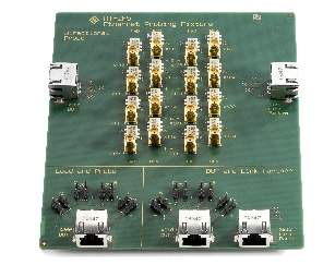
Figure 2: The R&S RT-ZF5 Ethernet probe fixture separates the full-duplex data streams of 100BASE-T1 communications. Source: Rohde & Schwarz
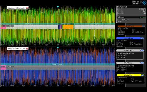
Figure 3: 100BASE-T1 decoding of full-duplex communications. The MAC frame is colored while the idle frames are gray. Source: Rohde & Schwarz
The signal streams that the probe extracts are still subject to the pre-distortion imposed by the equalizer in the 100BASE-T1 transmitter to protect their transport over the unshielded twisted pair. The next step is for the oscilloscope to equalize the signals to return them to their undistorted state, and then extract and display the transmitted data telegrams and idle frames. Correlation of the 100BASE-T1 signals with the content of the telegrams - coupled with extensive triggering capabilities that can, for instance, be used to display isolated telegrams based on their source or destination addresses –enables the powerful analysis and diagnostic capabilities increasingly needed for automotive Ethernet.
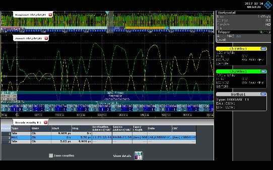
Figure 4: This screenshot shows the two levels of the differential 100BASE-T1 signal correlated with the decoded telegram content. Source: Rohde & Schwarz
100BASE-T1 decoding
100BASE-T1 decoding provides a way of revealing the timing relationship between bus communications and other signals. For example, the start time of an ECU can be determined by measuring the length of time between triggering an oscilloscope on the 12V supply and the arrival of the first valid telegram. A similar approach can be used to verify the stability of communications over the bus. In this case, the scope is configured to trigger on short-term interruptions of the supply voltage, so the developer can analyze the number of bus anomalies that those interruptions cause.
Electromagnetic interference can cause sporadic bus errors that are difficult to debug without further analysis. However, the ability to decode 100BASE-T1 communications means that developers can analyze bus communications across all of the OSI protocol layers, using the timing correlation of the measurements to identify coupling from interference sources.
Consider the measurement shown in Figure 5 where the MAC and idle frames of a 100BASE-T1 signal are correctly transmitted at the start of the recording. The data stream is then interrupted. In the lower signal, the frequency spectrum of the interfering signal (area marked in gray) is plotted, showing the cause - an interference peak at 2MHz. This combination of protocol-specific decoding with the range of analysis tools provided by the oscilloscope (e.g. frequency spectrum) simplifies debugging of complex issues such as intermittent
interference.
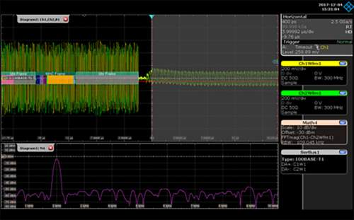
Figure 5: Pinpointing a sporadic interruption in bus communications by combining protocol analysis and frequency analysis. Source: Rohde & Schwarz
Summary
Automotive communications are becoming more complex as data rates rise. The emergence of the 100BASE-T1 automotive Ethernet standard is easing the bandwidth issues of existing in-vehicle bus systems, at the cost of more complex debug challenges.
Rohde & Schwarz has developed a trigger and decode bundle option for debugging 100BASE-T1 signals, which includes a probing fixture for nonintrusive signal access. This tool enables developers to correlate electrical signal measurements with the decoded contents of transmitted telegrams. As a result, users can analyze protocol content during debugging and quickly identify the causes of any bus errors that occur.
Author: Dr Ernst Flemming is the product manager for oscilloscopes at Rohde & Schwarz in Munich.